1. INTRODUCTION
Functional nanoparticles (NPs) have been used in various engineering and scientific research areas with unique optical, physical, and chemical characteristics [1-4]. Wavelength selectivity of the NPs is useful in selectively interacting with a specific wavelength of light [5]. The light interaction can also lead to unique plasmonic characteristics such as thermo-plasmonics where the absorbed optical energy is converted to thermal energy for local temperature changes [5]. The local heat generation by light has been proposed to open up various applications, including neuromodulation, cancer therapy, photochemistry, polymerase chain reaction, and so on [5-9]. In addition, the NPs can be easily chemically functionalized to implement selective chemical sensing. By integrating the chemically functional NPs with electronics, unique bioelectronics applications such as biosensors and bio-FETs have been suggested [10-12].
Despite the favorable characteristics and demonstrated applications of the NPs, one of the most significant limitations of using the NPs for bioelectronics is that conventional photolithography is not compatible with the NPs in micropatterning of the material. Beyond the feasibility demonstration in the laboratory, we must have efficient ways for micropatterning NPs. Inkjet-printing technology is a great candidate for the precision patterning of functional NPs. Most NP solutions are easily inkjet printable to form several tens of μm sizes of the NP patterns. Thus, microelectronic devices can be easily functionalized with inkjet-printed NPs. Moreover, with the capability of easily varying the deposited NP density, it is possible to precisely control the degree of the unique characteristics of the NPs.
To realize the functionalization of the microelectronics with the inkjet-printed NPs, it is essential to be able to control the NP assembly within the micro patterns precisely. Inkjet-printed NPs have long been used for forming conductive electrodes in printed electronics. For those applications, however, high-density NPs are inkjet-printed to reduce the porosity of the printed structures and form connected NPs. Due to the high density and low porosity, the assembly of the NPs within the printed patterns–i.e., how the NPs are distributed within the printed patterns during the drying of the printed ink–is not of concern. However, the characteristics of the functional NPs strongly depend on how the NPs are assembled. For example, the unique plasmonic characteristics of a single NP will not be maintained when multiple NPs are closely placed. The plasmonic coupling effect can occur for the NPs to act as bigger NPs [13]. Therefore, to keep the unique single NP characteristics in a group of NPs, many efforts have been made to achieve uniform assembly or distribution of the NPs within the NP coatings.
Optimization of the assembly of the NPs within the inkjet-printed micropatterns, however, is more challenging than when the NPs are coated as a continuous film. During the drying of the microscale NP inks, unequal evaporation rate around the boundary of the ink droplet and several mechanisms for the flow of ink within the droplet often make it difficult for the NPs to be assembled uniformly. The most studied mechanism is the coffee-ring effect. Due to the more substantial solvent evaporation rate on the side of the spherical cap-shaped printed droplet than in the center, a replenishing flow of solvent is formed outwards from the center. This flow induces the movement of the NPs towards the edge of the droplet, resulting in a higher concentration of the deposited NPs at the edge, called coffee-ring or coffee-stain. One prerequisite for the coffee-ring effect is contact line pinning (CLP) [14]. The shape of the dried NP patterns, therefore, is identical to the shape of the pinned contact line edge with a deficient concentration of the NPs inside. To suppress the coffee-ring effect and induce the uniform assembly of the NPs, the co-solvent system is used to generate Marangoni flow which acts in the opposite direction of the solvent replenishing flow [15].
However, recent studies have reported that the co-solvent system implementation is not enough to achieve uniform assembly of the NPs within the printed patterns. Several studies experimentally validated that electrostatic interactions within the NP ink also play a significant role in the particle assembly in sessile droplets [16-19]. For example, depending on the combinations of either attractive electrostatic force or repulsive between the particles and the added surfactant, coffee-ring deposition or disk-like uniform particle assembly is achieved [16,17]. In these works, it has been reported that the added surfactants modify the surface charge of the NPs in ink, and the interaction between the substrate surface and the NPs is also significantly affected. When the attractive interaction between the NPs and the substrate surface is formed, a more uniform assembly of the particles is observed. In addition, the pH level of the ink solution was also tuned to control the electrostatic interaction between the colloidal particles and the substrate [18,19]. Also, a more uniform assembly of the particles was observed when the attractive electrostatic force was implemented. Therefore, electrostatic interaction must be controlled well to uniformly assemble the inkjet-printed functional NPs in addition to the suppression of the coffee-ring effect. However, the two methods of adjusting the assembly of the NPs, the addition of surfactants to the printing ink and the control of pH level, have crucial limitations. When these methods are used, we cannot separately modify the surface charge polarities of the NPs and the printing substrate as the surfactants and the pH level affect the surfaces of the particles and the substrate simultaneously. Therefore, it is impossible to carefully study the effect of the electrostatic interaction between the NPs and the printing substrate on the assembly of the NPs. Moreover, many applications of the inkjet-printed functional NPs include bioelectronic or chemical sensors which may not allow the usage of surfactants or the freedom to vary the pH level as they can be toxic or sensitive to chemical reactions, respectively. Therefore, there is a need for providing individual modification of the surface charge polarity of the printed functional NPs and the printing substrate for an in-depth understanding of the inkjet-printed NP self-assembly and its broader range of applications.
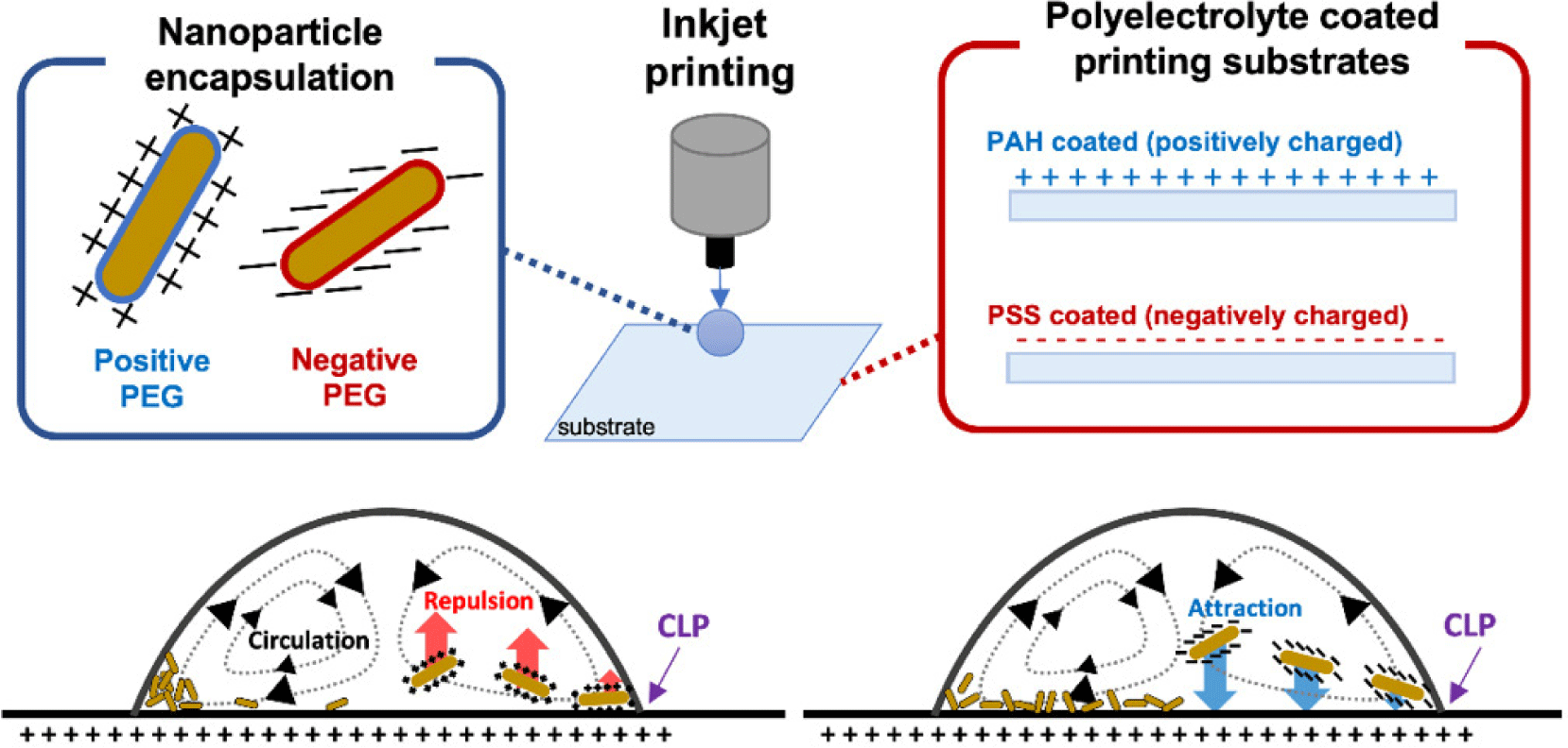
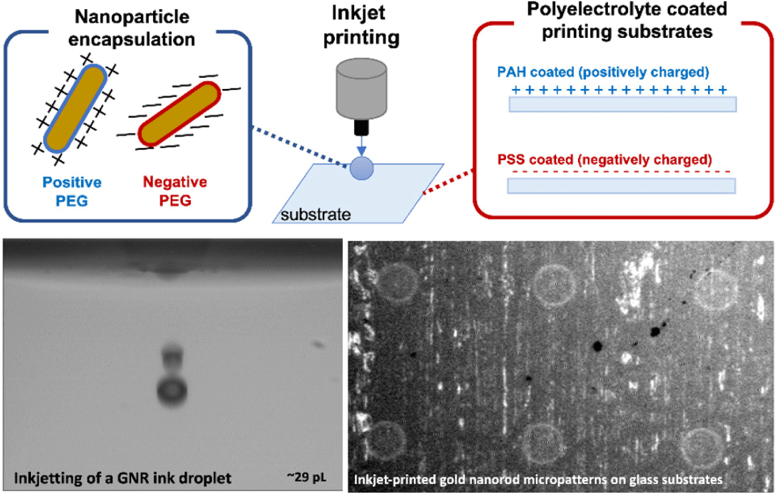
In this work, we studied the effect of the electrostatic force between the inkjet-printed nanoparticles and the printing substrate on the uniform assembly of inkjet-printed nanoparticles. Unlike the previous studies, we used biocompatible nanoparticle encapsulation coatings and substrate surface coatings to modify the surface charge polarities of both independently. With this experimental design, it is possible to confirm the driving force of the uniform NP assembly and suggest a proper methodology to achieve efficient unique functionalities of the NPs. As illustrated in Fig. 1, we used the two coating methods for the NP and the printing substrate, respectively, to implement both positive and negative surface charges; we inkjet-printed both charged nanoparticles (+, −) on both charged glass substrates (+, −), and we analyzed the assembly of the micro patterns of the dried nanoparticles.
2. METHODS
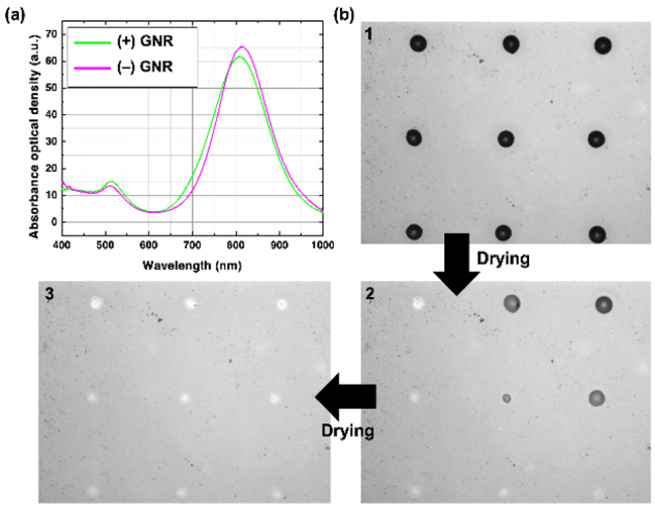
In this work, as the inkjet-printed nanoparticles, we used near-infrared (NIR) absorbing gold nanorods (GNRs) which are often used particularly in biomedical engineering applications [20-24]. The GNRs are synthesized following the previously reported seed-mediated synthesis methods to have approximately 19 nm×71 nm in width and length, respectively [7,20]. We have prepared two different GNRs: one with positively charged encapsulation, and the other with negatively charged encapsulation. The positively charged encapsulation was amine polyethylene glycol thiol (NH2-PEG-SH) (PG2-AMTH-5k, Nanocs), and the negatively charged encapsulation was methoxy polyethylene glycol thiol (mPEG-SH) (PG1-TH-5k, Nanocs). As shown in Fig. 2(a), the maximum absorbance wavelength for the positively charged GNR ink was 808 nm, and for the negatively charged ink was 816 nm, both of which are in the commonly used NIR range. The slight differences in the peak wavelength were possibly due to the variation in the nanorod growth time at room temperature and the different thicknesses of the polyethylene glycol thiol encapsulation layers. The surface zeta potential values of both encapsulated GNRs were measured to be +24.7 mV and −24.5 mV in deionized water (Zetasizer Nano ZS, Malvern), respectively. Both types of the inks were prepared to have nearly the same concentration (less than 5% difference), confirmed optically.
Synthesized GNRs are formulated to inkjet printable inks by dispersing them in a co-solvent system. The ink solvent was a mixture of deionized water and ethylene glycol (EG) at a 5:5 ratio. This solvent mixture ratio was reported to show a dimensionless inkjet stability parameter, Z number defined as the ratio of Reynolds number to the square root of the Weber number, to be less than 10 [20]. The addition of the high boiling point and lower surface tension solvent, EG, was reported to be suppressing the coffee-ring effect [20]. The prepared GNR inks were filtered with 5 μm pore sizes to avoid clogging the inkjet printing nozzles. Also, the concentration of the GNR inks was kept low to prevent nozzle clogging. We used an inkjet printing system (UJ200MF, Unijet) with piezoelectric inkjet nozzles (MJ-AT-01 series, MicroFab). We used a 50 μm size orifice nozzle to jet approximately 29 pL of the prepared GNR ink droplets. We jetted multiple droplets on the same spot to increase the density of the nanoparticles until the printed particles were clearly visible under the microscopes (i.e., more than 10 droplets).
Polyelectrolyte layer-by-layer (LbL) coating was used to modify the surface charge of the printing glass substrates. Starting with a commercial 75 μm-thick glass coverslip (0101030, 18 mm×18 mm, Marienfeld-Superior), we dip-coated the substrates with the following two polyelectrolyte solutions. PAH solution for positive charge coating and PSS solution for negative charge coating. Both polyelectrolyte solutions were 10 mM NaCl concentrated for a more uniform polyelectrolyte coating. Starting with the positive PAH coating, at least 10 bi-layers were LbL coated interchangeably. The surface coating was finished with the last polyelectrolyte layer of choice for the surface charge polarity. For example, the substrate is positively charged when the PAH coating was the last step. The substrate is negatively charged when the PSS coating was the last step.
As shown in Fig. 2(b), the prepared two GNR inks were inkjet-printed as independent dot patterns on both prepared substrates. After some time, the printed droplets dried and showed the micropatterns of the GNRs on the substrates. The dried printed GNR micro patterns were analyzed as follows. Optical analyses were performed on inverted microscopes with a phase-contrast objective for phase-contrast (PC) images and a dark-field illuminator for dark-field (DF) images for more precise observation of the nanoparticle distribution within the micro patterns. To quantify the NP distribution, we used scanning electron microscopy (SEM) to obtain high-resolution images of the printed NPs and count the density of the NPs at different positions of the micro patterns of the NPs.
3. RESULTS AND DISCUSSION
We first inkjet-printed the two differently surface-charged GNR inks ((+)GNR as positively charged, (−)GNR as negatively charged) on the positively charged PAH terminated LbL coated glass substrate. Total of 12 droplets of 29 pL were inkjet-printed on the same spot to form an array of micro dots (approximately 190 μm in diameter for (+)GNR, and 170 μm for (–)GNR), as shown in Fig. 3. As previously reported, the inkjet-printed droplets on the LbL coated polyelectrolyte showed contact line pinning (CLP) to allow an excellent definition of the micro patterns [20]. By optically imaging the printed dots through both PC and DF images, we qualitatively analyzed the distribution of the NP assembly within the inkjet-printed micro patterns. The printed droplets showed nearly similar diameters due to the same ink solvents. Therefore, the two printed GNR ink patterns showed no differences from macroscopic observations. However, the PC and DF microscopic images of the inkjet-printed (+)GNR and (–)GNR patterns showed apparent differences in the uniformity of the nanoparticles within the pattern. It is most noticeable that the negatively charged GNRs are more uniformly distributed within the microdot patterns, comparing the inner area with the edge.
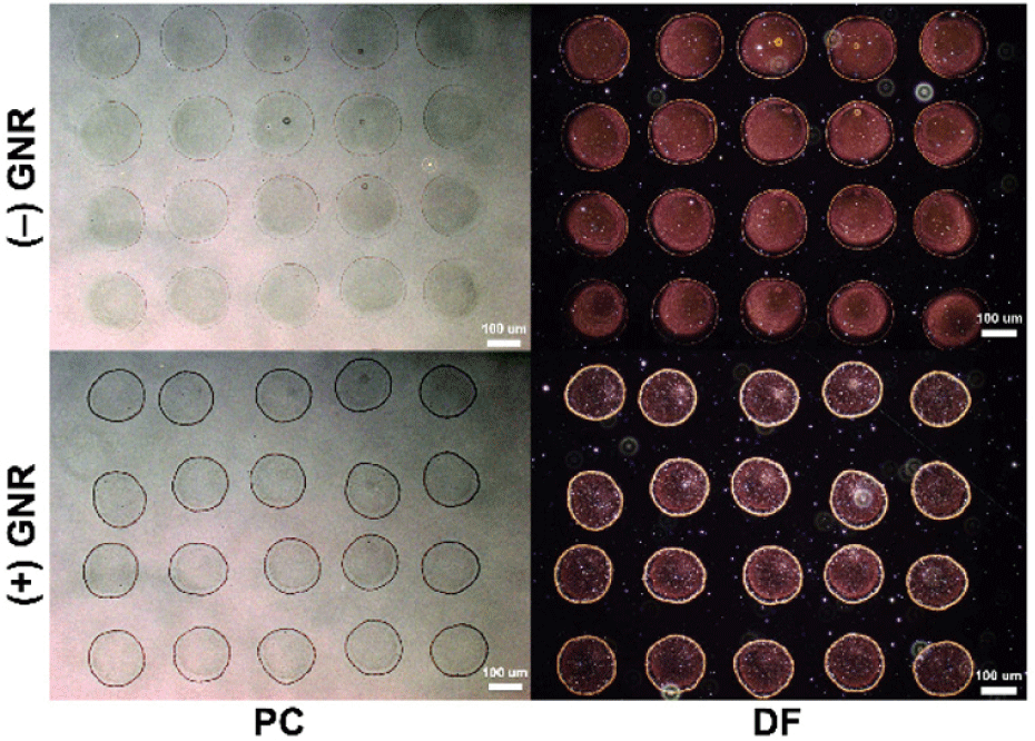
On the other hand, when the positively charged nanoparticles are dried within the micropatterns, we observed that a larger amount of the GNRs is accumulated at the edges of the micro patterns. The accumulation is represented as darker colors in the PC images and brighter gold colors in the DF images. Therefore, despite being printed and dried from the exact formulation of the ink solvents and on the same surface-charged substrates, the assembly of the GNRs within the micropatterns during drying was significantly different. With the controlled experiments, we can conclude that the electrostatic interaction between the GNRs and the printing substrate is crucial in assembling the particles.
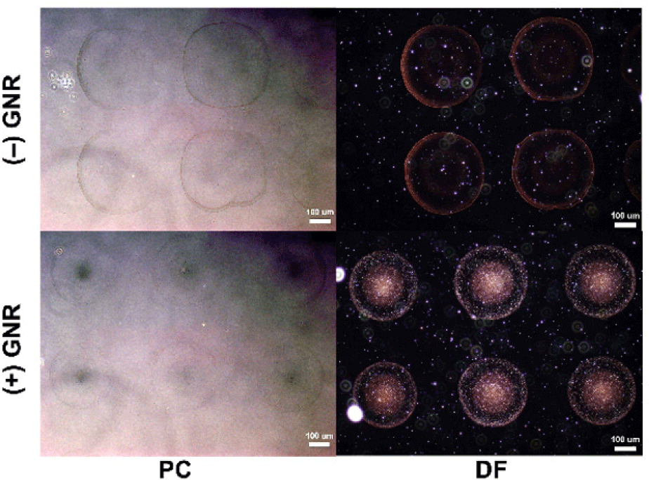
Next, we inkjet-printed the same two GNR inks on the negatively charged PSS terminated glass substrate and analyzed the nanoparticle assembly characteristics within the micro patterns (total 12 droplets of 29 pL for each; approximately 320 μm in diameter for (+)GNR, and 370 μm for (−)GNR). Similar to the printing results on the positively-charged substrate, we also observed a significant effect of the electrostatic interaction between the GNRs and the substrates on the uniformity of the assembly of the nanoparticles within the micropatterns. As shown in Fig. 4, when the negatively charged GNR ink was printed on the same negatively charged substrate surface, the microscope images show that there is not much concentration of the GNRs observed within the micro patterns. Still, most of the GNRs seem to be located at the edges. On the other hand, when the positively charged GNRs were printed on the oppositely surface-charged substrate, a significant portion of the GNRs are observed within the micro patterns, particularly near the center areas. In sum, from the two different printing experiment results, we consistently observed that the electrostatic attraction between the NPs and the printing substrate leads to more coverage of the NPs within the micro patterns and a more uniform assembly of the NPs. On the other hand, when the electrostatic repulsive force was implemented between the NPs and the printing substrate, during the drying of the printed ink, the NPs seemed to prefer being accumulated near the pinned contact lines rather than the inner areas.
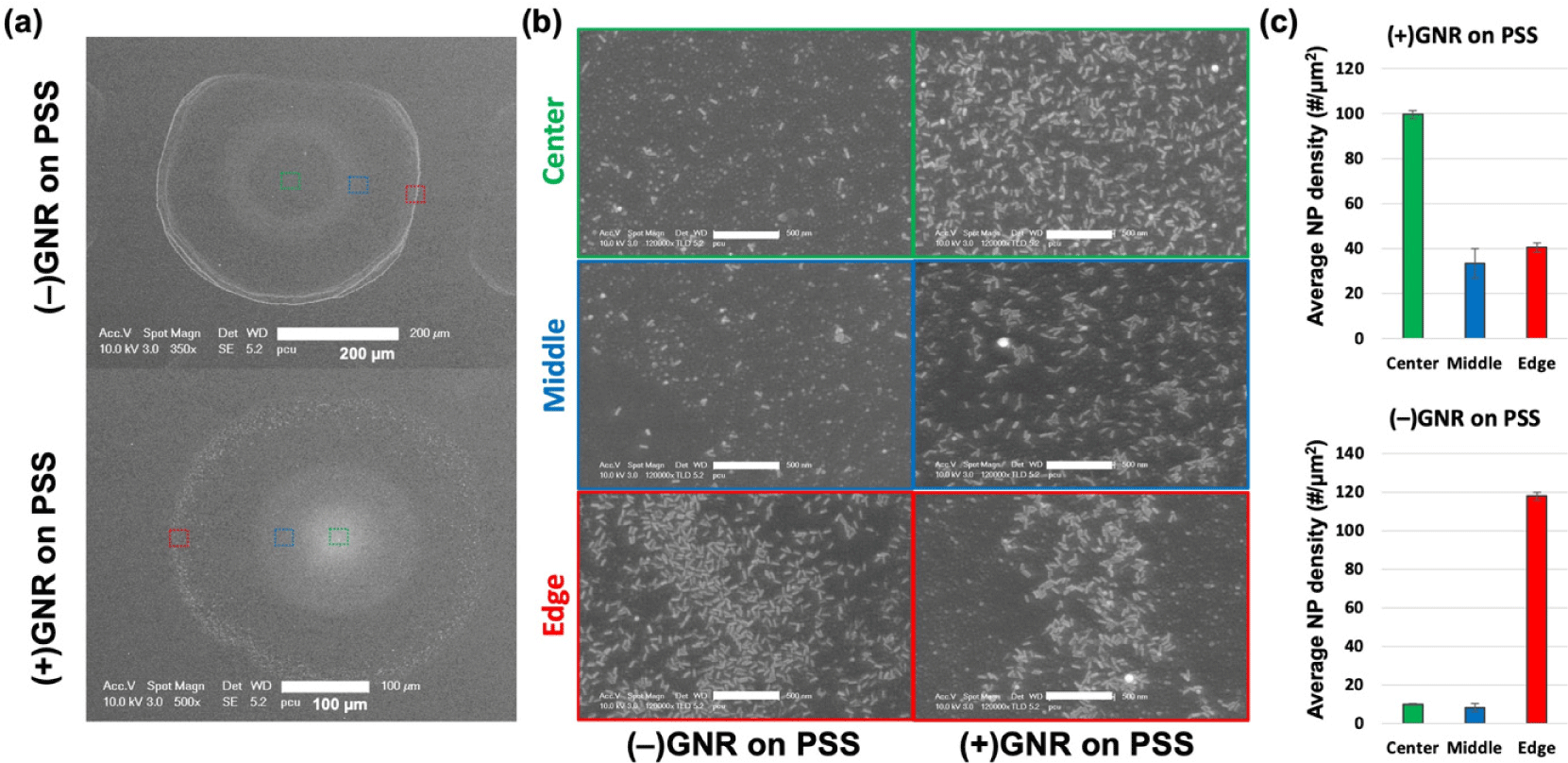
We further took on the quantitative analysis of the printed and dried GNR assembly within the micro patterns. From the SEM images of the printed GNR patterns in Fig. 4, we counted the GNRs in given areas at different regions within the micro patterns (center, middle, and edge). Each region was scanned three times, and the average GNR density was compared. As shown in Fig. 5, the representative SEM images for the entire micro dot patterns (Fig. 5(a)) and the three regions at much higher magnification (Fig. 5(b)) also showed the same uniform and non-uniform GNR assembly results as the optical microscopic images in Fig. 4. The average number of counted GNRs within one μm2 area also showed the significant differences as presented in Fig. 5(c). When the electrostatic repulsion was implemented (i.e., (−)GNR on PSS), the three regions showed vastly different densities. The edge region showed a more than ten times higher population of the GNRs than the other inner regions. On the other hand, when the electrostatic attraction was implemented (i.e., (+)GNR on PSS), the three regions showed a much smaller difference.
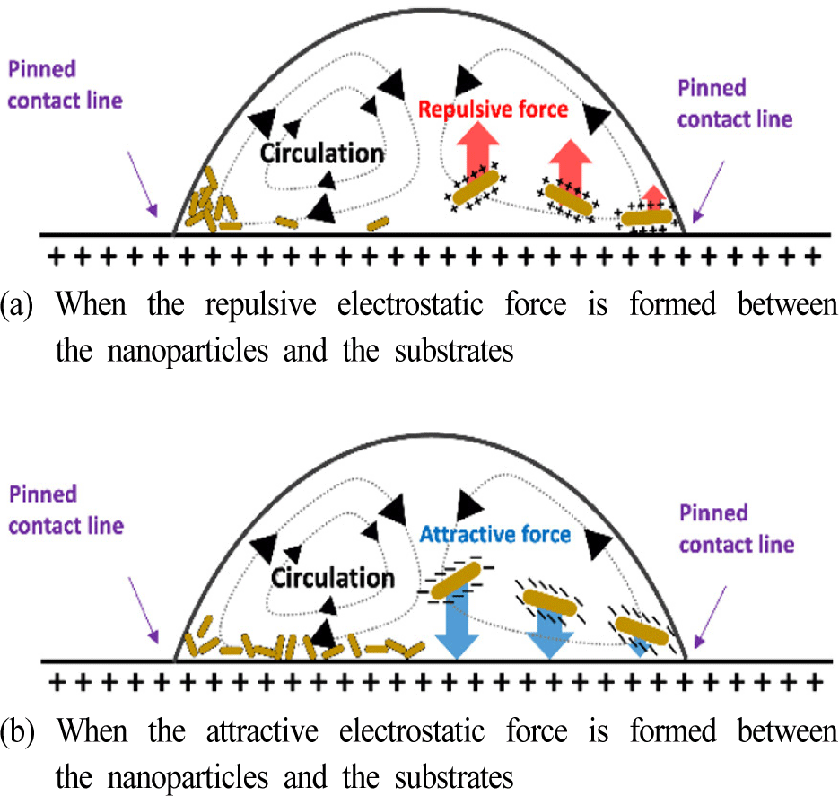
The mechanism of our observations on the NP assembly during drying in the two different electrostatic interaction conditions can be explained as illustrated in Fig. 6. First, the LbL coated substrates implement contact line pinning. Once the CLP is satisfied, during the drying of the droplets, circulation of the solvent is induced due to the higher evaporation rate near the edges and the Marangoni flow from the co-solvent system. During the internal circulation, the GNRs or NPs also circulate until the droplet is thoroughly dried. During that process, the electrostatic interactions between the NPs and the substrate play essential roles. When the electrostatic repulsion is formed, as described in Fig. 6(a), the NPs are pushed away from the surface of the inner area, thus being left near the pinned contact lines. We think it is why we observed a significantly higher concentration of the NPs near the edges in Fig. 3 and Fig. 4. On the other hand, when the attractive electrostatic force is formed during the circulation, the NPs are attracted to the surface of the inner area, thus being attached to the inner area and leading to a more uniform assembly of the NPs within the printed micro patterns.
Compared to previous works in the literature on studying the NP assembly during drying, our experiments in this work are mainly different in two things. First, the surface charges of the NPs and the substrate surface were controlled separately by using different chemical capping materials for the NPs, and different LbL coated polyelectrolyte terminations. Unlike the previous works, we did not use surfactants and did not significantly modify the pH levels to control the electrostatic interactions. The surfactants and the pH level cannot separately control the surface charges of the NPs and the substrates as they simultaneously modify the surface characteristics of the NPs and the substrate. Therefore, it was impossible to solely study the effect of the electrostatic interaction on the NP assembly during drying. In our experiment design, the electrostatic interaction was more systematically controlled. Second, we studied the functional NP ink conditions, which are more suitable for bioengineering applications. Because the surfactants can be toxic, and so are the extremely varied pH values, our methods can be used for bioengineering applications where functional nanoparticles are needed to be micropatterned and uniformly assembled.
4. CONCLUSION
In this work, we systematically studied the effect of the electrostatic interactions between the printed nanoparticles and the printing substrate surfaces on the uniform assembly of the printed nanoparticles after drying. Significant differences between electrostatic attraction and repulsion were observed in the nanoparticle distribution within the printed micropatterns. The attractive force allows much more uniform nanoparticle assembly within the micropatterns, whereas the repulsive force leads to accumulated nanoparticles near the edges. The observation is consistent with previous studies, although we neither added surfactants nor modified pH levels. The fundamental understanding of the printed nanoparticle assembly helps us to fabricate uniformly distributed micropatterns of functional nanoparticles, especially in bioengineering or bioelectronics applications where surfactants need to be avoided, and the pH level needs to be fixed.

